1 8 To Xlr Adapter Wiring Diagram
This article shows the XLR Pinout diagrams for both 3-pin and 5-pin connectors. This wiring configuration gives you a.

Pin By Shaiful Nizam On Audio Studio Wiring Diagram Diagram Subwoofer Wiring
If the signal source is equipped with a.

1 8 to xlr adapter wiring diagram. I fly ATR aircraft which has a XLR 5 headset connector aka airbus adapter and I want to use my own headset while flying. The uninsulated ground wire should go to pin 1 the red wire to pin 2 and the black wire to pin 3. The common elements in a wiring diagram are ground power supply wire as well as link outcome tools buttons resistors reasoning entrance lights etc.
This can be done by either soldering the shield and negative wires of the XLR to the sleeve of the plug. The two terminal 14 connector is commonly referred to as the TS or Tip-Sleeve version. Connect the Positive Negative and Ground wires from each XLR connector to the terminal adapter according to the diagram shown.
Insert stereo cable unbalanced. Diagram astatic mike wiring uhf transmitter 5 pin input jack 3 xlr cable microphone mono output green bullet mics building your own mic adding a or tape level conductor to 3pin connector shure sm58 8 stereo unbalanced 5mm ipad iphone ipod touch for what do microphones plug into full date one two and three wire does it aircraft pinout. Youll also discover each XLR pins polarity.
If the signal source is equipped with a pseudo balanced output stage. 14 TRS to RJ-45 Female. Problem is my headset has a GA-type plugs PJ-55 for the phone - 025635 mm - aka M6424-1 and PJ-068 - 0206525 mm for the mic aka M6425-1 I know there are tons of commercially.
A checklist of electric signs and also summaries could be found on the electrical symbol page. It has 3 wire terminals and is standard. The most comon way to wire a 3-pin XLR to a 14 inch 65mm mono plug sometimes called a jack plug is to join the negative and shield together.
Microphone cable balanced according to iec-norm. XLR to 14 Mono Plug. The surrounding shield should be soldered to pin 1.
Xlr to 1 4 mono plug the most comon way to wire a 3 pin xlr to a 1 4 inch 6 5mm mono plug sometimes called a jack plug is to join the negative and shield together. XLR ADAPT-XLRM ADAPT-XLRF XLR ADAPT-RCA RCA or Phono ADAPT-RCA RCA or Phono ADAPT-TRS ADAPT-MINI TRS - 14 or 18. Wiring diagram xlr to usb wiring diagram 9 out of 10 based on 20 ratings.
The three pin and five pin XLR pinout is a very standard connection used for audio mic level line level 3 pin and lighting control DMX 5-pin applications. XLR 5 to GA headset adapter. Aeroelectric Connection Aircraft Microphone Jack Wiring.
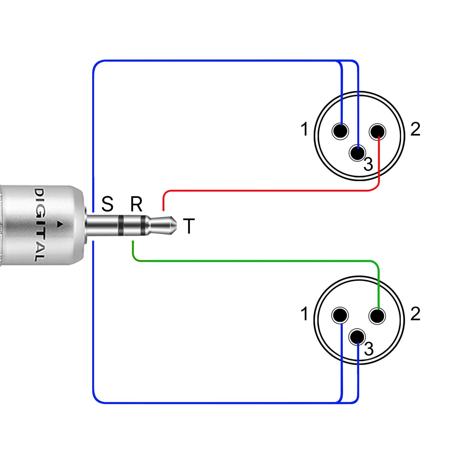
XLR to 14 TRS Connector wired for balanced mono The usual way to connect a 3-pin XLR to a 14 TRS AKA stereo jack plug is to use the following pin allocation. The XLR connector is pretty straight forward. The 14 connector on the other hand can have 2 or 3 wire terminals and is not standard.
XLR pin 1 to 14 plug sleeve. Usb to headphone jack wiring diagram. Balanced audio cable designed for installs usually has a black white and ground wire.
Before wiring the plug it is a good idea to insert the metal part into a suitable rca socket in a clamp and slide the plug shell and strain relief coil onto the cable first. Click Refresh To Reload Complete Large Pictures. Below are the image gallery of wiring diagram for usb plug if you like the image or like this post please contribute with us to share this post to your social media or save this post in your device.
3 to xlr wiring diagram pin 1 pin 1. Jack cable balanced stereo. The Xlr Wiring Diagram Pdf that we provide for you will be ultimate to give preference.
5 pin 3 pin XLR wiring pinout information. The above diagram shows you the pin numbering for both Male and Female XLR connectors from the front and the rear view. The TS connector is an.
IPad iPhone iPod Touch Microphone Adapter Wiring Diagramwiring diagrams audio cable. Audio CableConnector Wiring Diagrams Female Balanced XLR TO Male Unbalanced 14 63mm or 35mm Jack Fig. In the wiring diagram below note that considerations for the split pair wiring that a properly built RJ45 Ethernet cable needs to follow.
This reading wiring diagram is your chosen wiring diagram to accompany you when in your free time in your lonely. Adapter cables are custom-made to facilitate speedy hookup of audio sources to Telos Alliance Mixed Signal Node and AESEBU Interfaces. The three terminal 14 connector is commonly referred to as the TRS or Tip-Ring-Sleeve version.
This kind of wiring diagram can help you to heal the lonely. XLR Male to RJ-45 Female. READ Ge Motor Starter Wiring Diagram.
XLR pin 2 to 14 plug tip. PLUG Classic 45 Classic iC Classic Pro iCM GM 45 GM Vintage HM-10 Dual Handi MIc 45 Handi MIc iC Handi Mic PRO Handi Mic Pro Plus PR 20 3040781 Heritage The Fin Alinco 8 pin round CC-1 K CC-1 K CC-1 K CC-1 K CC-1 K CC-1 XLR-K PC 18 HSTA - CELL HSTA-PC HSTA-PC CC-1 I 316 stereo CC-1 C CC-1 C CC-1 C CC-1 C 4 pin CC-1 T CC-1 T CC-1 T CC-1 T Drake CC-1 C. Standard-length short Stereo analog cables.
The Studio Wiring Solution from 2- Positive Pin-1 Pin-2 Shield Pin-3 Pin-6 Shield 1 2 3 2 1 3 3- Negative Tip Male LEFT or AES Green Band Balanced. XLR pin 3 to 14 plug ring. The rear view is the end you solder from Here are the connections on each pin.
The following Telos part numbers are available for 8 inch 200mm cables.

4x12 Speaker Cabinet Wiring Inspirational In 2021 Wiring Diagram Speaker Speaker Wire

How To Make Xlr Cables Part 3 Single Core Cable To Ts Rca Youtube

My Old Phone Arduino Phonoduino Old Phone Arduino Audio Amplifier

Diy How To Make Your Own Audio Cables Soldering Xlr And Ends Audionewsroom Anr Wiring A Plug Audio Cables Audio
Wiring Diagram Xlr

Http Www Mediacollege Com Audio Connection Jack Stereo Rca 2 Html Electrical Schematic Symbols Rca Connector Electronics Projects Diy

Https Www Gearslutz Com Board Attachments Connectors Cables Stands Accessories 522437d1451935218 How Should 3 Core Xlr Cables W Diy Amplifier Wire Cable Wire

Trs Wiring Diagram Como Consertar Fones Fones De Ouvido

1 8 Stereo Plug Wiring Diagram Earphones Wire Usb Headphones Stereo Headphones

Amazon Com Tisino Dual Xlr Female To 3 5mm Trs Stereo Y Adapter Cable Unbalanced 2x Xlr To 1 8 Inch Mini Jack Y Splitter Break Stereo Microphone Price Tracker

Benchmark Rca To Xlrm Adapter Cable For Analog Audio Pin 3 To Rca Shield Rca Rca Connector Adapter

Electronic Circuit Projects Electronic Engineering Audio Cables

35 Mm Stereo Wiring Diagram Wiring Diagram Electronic Circuit Projects Trs
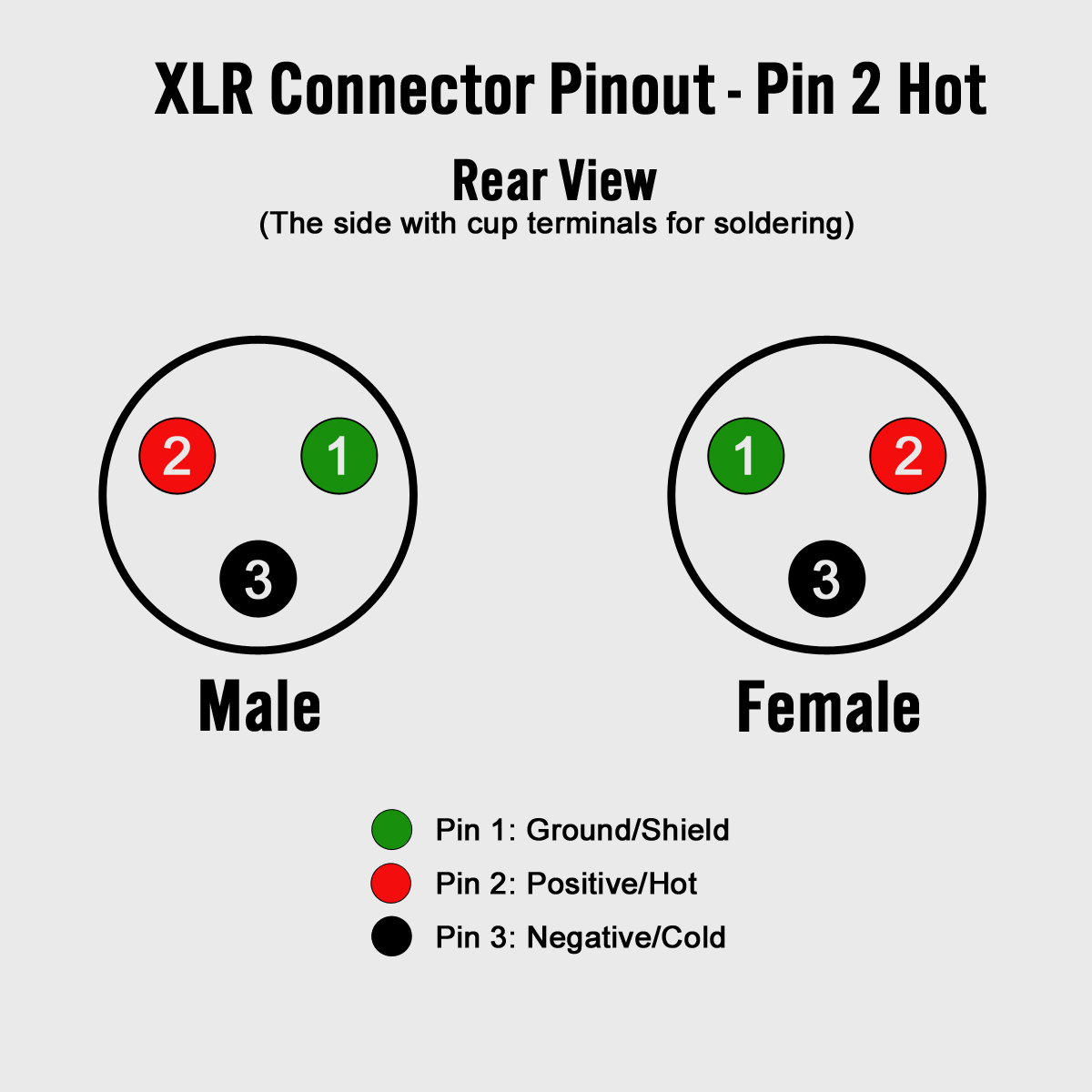
Diagram Speakon To Xlr Cable Wiring Diagram Full Version Hd Quality Wiring Diagram Diagramman Prolococusanese It

Audio Jack Wiring Diagram Http Bookingritzcarlton Info Audio Jack Wiring Diagram Wiring Diagram Diagram Wire
Tnp 3 5mm Trs To Xlr Adapter Cable 6ft Male To Male Stereo Xlr Pinout Breakout Y Adapter Splitter Dual Xlr To 3 5mm 1 8 Trs Auxiliary Aux Headphone Audio Jack Plug Converter

Nu9n Transmitter Essb Ssb Hi Fi Mid Fi Lo Fi Audio Processing Electrical Circuit Diagram Diy Amplifier Hifi

Electronic Schematics Security Cameras For Home Diy Headphones

Pin Di Wiring Diagram